

Validation of On-Wafer Vector Network Analyzers
|
Validation of On-Wafer Vector Network Analyzers
J. Randy Fenton Cascade Microtech, Inc.
AFTFG 68th Microwave Measurement Conference Nov. 28 – Dec. 1, 2006
|

|
Investigate a proposed VNA comparison technique to validate on-wafer VNA systems Outline a detailed procedure and define terms Explore limitations Show sample results Provide conclusions
|
1
|
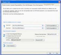
A convenient calibration validation check Preferably automated • Quick and easy • Generate insightful reports
|
2
|
|
Apply comparison technique described in
“A Method for Comparing Vector Network Analyzers” D. C. DeGroot, R. B. Marks and J. A. Jargon 50th ARFTG Conference Digest, pp. 107-114 Portland, OR, December 1997 to an On-Wafer Environment
|
3
|
Measure a family of validation structures on both VNA systems Calculate the Error Vector Magnitude (EVM) difference between the two systems for each structure Find maxEVM for entire family of structures Determine Repeatability bounds for each system Compare the EVMs and maxEVM to the sum of the Repeatability bounds
|
Criteria: Are the measurement differences between the VNAs bounded by the overall repeatability limits?
Yes – the Test system is validated for these devices. No – the Test system has residual errors unaccounted for during calibration that are significant relative to the Reference system.
|
4
This comparison technique is only valid for the specific set of validation devices used during the experiment. Assumes the Reference system has trusted accuracy. However, for many users this quick and convenient validation check provides enough important feedback to either gain or lose confidence in their measurement system.
|
ERROR VECTOR MAGNITUDE (EVM) difference between two measurements is defined as:
Where: • Srefij are S-Parameter data files from Reference system • Stestij are S-Parameter data files from Test system
|

5
|
ACCURACY is the level of agreement of a measured or calculated quantity to its actual true value.
MEASUREMENT ERROR is closely related to accuracy and is defined as the difference between a measured value of quantity and its true value.
|
|
MEASUREMENT REPEATABILITY is the variation in multiple measurement results taken by the same instrument on the same item and under the same conditions. • A measurement may be said to be repeatable when this variation is smaller than some agreed limit. • Repeatability conditions1 include: • the same measurement procedure • the same observer • the same measuring instrument, used under the same conditions • the same location • repetition over a short period of time.
1Guidelines for Evaluating and Expressing the Uncertainty of NIST Measurement Results
|
6
|
MEASUREMENT REPRODUCABILITY is the variation in multiple measurement results taken by different persons or instruments on the same item and under the same conditions.
• A measurement may be said to be reproducible when this variation is smaller than or equal to some agreed limit.
|
Repeatability and reproducibility do not necessarily imply accuracy.
Measurements may be repeatable and reproducible yet inaccurate.
To use reproducability as a validation test, the Reference system must be trusted.
|
7
|
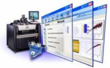
WinCal XE calculates the estimated repeatability bounds for VNAs using the method described in
“Calibration Comparison Method for Vector Network Analyzers” R. B. Marks, J. A. Jargon, and J. R. Juroshek 48th ARFTG Conference Digest, pp. 38-45 Clearwater, FL, December 1996
|
|
Two types of repeatability bounds: • Device Dependent Bounds: Apply the error terms to the S-Parameter measurement data for each particular device • Worst Case Bounds: Apply the error terms to an S-Parameter data set with all terms equal to one
|
8
|
The overall repeatability bound was determined by adding Reference system bound (∆refR) and Test system bound (∆testR) using device dependent and worst case methods. ∆refR + ∆testR = Overall Repeatability Bound
|
|
|


9
40ps Transmission Line 40ps Open Stub Attenuators: 10dB, 20dB Resistors: 12.5Ω , 25Ω , 50Ω Offset Short Inductor Capacitor Offset Resistors: Long Offset 25Ω Resistor The majority of these structures are available on the Cascade Microtech 101-190 and 005-016 Impedance Standard Substrates
|
|
10
|
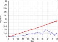
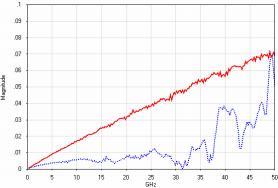
Inductor S11 EVM vs. inductor device-dependent sum of repeatability bounds
|
|
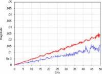
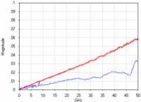
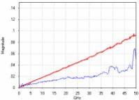
Capacitor S11 EVM vs. capacitor device-dependent sum of repeatability bounds
|

11
|
|
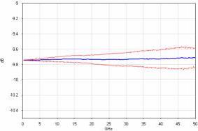
10dB Reference system data with 10dB Reference system device-dependent repeatability bounds
|
12
|
Test system reproduced Reference system results within repeatability bounds Test system can be trusted for measurements of these types VNA comparison technique proved to be useful and insightful as a validation and troubleshooting check
|
|
Validation technique only valid for devices measured Worst case repeatability bounds much more conservative compared to device-dependent repeatability bounds VNA residual errors are device dependent
|
13
|
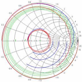
If possible, choose validation structures that resemble your device under test • Choose validation structures that cover different regions of the Smith chart • Choose validation structures with varying levels of attenuation Automate using WinCal XE to make the procedure quick and insightful
|
|
This technique would also be useful for on-wafer round-robin inter-laboratory measurement system comparisons Future work will include comparing on-wafer VNAs employing different calibration algorithms
|
14
|
Test system reproduced Reference system results within repeatability bounds Test system can be trusted for measurements of these types Validation technique only valid for devices measured Worst case repeatability bounds much more conservative compared to device-dependent repeatability bounds
|
|
VNA residual errors are device dependent If possible, choose validation structures that resemble your device under test • Choose validation structures that cover different regions of the Smith chart • Choose validation structures with varying levels of attenuation Automate using WinCal XE to make the procedure quick and insightful
|
15
|
VNA comparison technique proved to be useful and insightful as a validation and troubleshooting check This technique would also be useful for on-wafer round-robin inter-laboratory measurement system comparisons Future work will include comparing on-wafer VNAs employing different calibration algorithms
|
16